With Veeam Cloud Connect, service providers can offer Disaster Recovery as a Service (DRaaS). With DRaaS, service providers act as a disaster recovery target for their customers, enabling them to leverage Veeam replication to host a DR copy of their VMs.
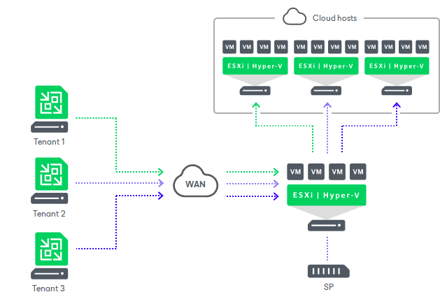
Some of the major building blocks of DRaaS include hypervisor, compute, storage, and networking. Veeam Cloud Connect (VBR with a Cloud Connect license) enables service providers to multi-tenant all these DRaaS components. Service providers can add their hypervisor, compute, storage, and virtual networking into the Cloud Connect server and provision it to their tenants (customers) as a cloud host.
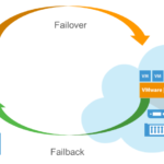
While configuring these components is relatively straightforward, the networking piece often raises many questions as it requires involvement and expertise from the networking team. During the failover process (when the production VM is down and the replica at the DR site is turned on), Veeam uses a component called the Network Extension Appliance (NEA).
In this blog, I aim to cover how to configure Veeam DRaaS from both the service provider and tenant perspectives. Additionally, I will share my learnings on the NEA from a networking standpoint. As someone who is not a networking expert, this was a steep learning curve for me. I hope others in a similar position find this information useful.
What is NEA?
The NEA is a Linux-based auxiliary VM created on virtualization hosts where tenant VMs and their replicas reside. Think of the NEA as a virtual router/firewall. It is essentially used in two ways:
Partial Failover: When only one or a subset of VMs are failed over, the NEA is used for communication between the failover VM and the VMs still running on the production side.
Full Site Failover: When the entire production site is down, the NEA provides internet access to and from the replica VM.
Additionally, the NEA is used to segregate traffic between tenants by leveraging VLAN and port groups.
Lab Setup
All testing was done in my home lab, which has a basic setup with a single IP range, public IP, and VLAN. To make it as close to a real-world setup as possible, I leveraged the OPNsense firewall to emulate multiple LANs and WAN connections.
The NEA will be deployed in both the tenant and service provider environments.
- On the tenant side, an NEA will be created for each production network.
- On the service provider side, there will be only one NEA per tenant. For each network on the tenant side, the NEA will have a separate NIC, and each NIC will be connected to its own port group
The scenario I am trying to emulate involves the tenant side having 2 LANs that will failover into the DR environment on the service provider side.
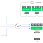
Below is how my lab is configured. We will be refering back to this through out this blog and will start making more sense as we go about configuring the DRaaS components

Configuring Service provider
Before proceeding with any settings on the service provider side, we will first set the password for the NEAs, ensuring we can log in later for troubleshooting.

The settings configured on the service provider side include:
Hardware Plan
- Specify CPU and memory allocation (compute)
- Specify storage allocation
- Specify network allocation
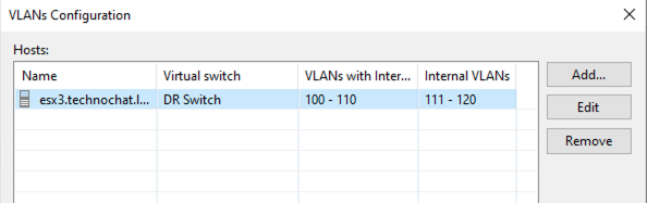
For the purpose of this blog, I have set up one internet access and one internal network. As the name suggests, the VMs in internet VLAN can access internet, while the VMs in internal VLAN cannot. The VM with internet access enabled will have a Source NAT created during the failover. We will discuss the NAT rules later in this blog series.
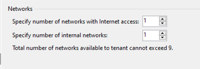
And I have allocated VLANs 100-110 as internet VLAN and 111-120 as internal VLAN.
Creating a Tenant Account
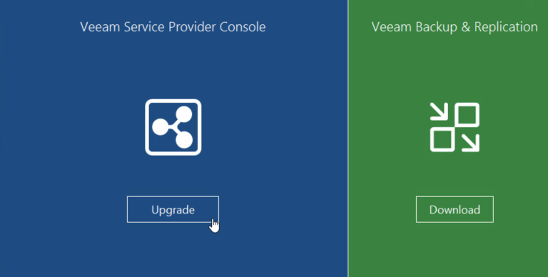
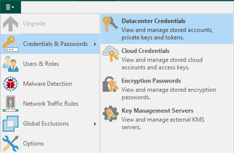
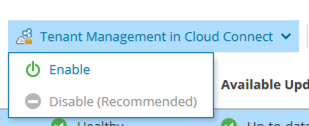
If you already have the Veeam Service Provider Console configured, please note that you need to enable tenant management on VBR. All the necessary building blocks of a DRaaS offering can only be created and managed from the VCC console.
Subscribe the tenant to a hardware plan
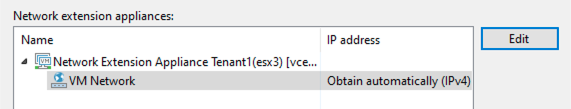
In the next step, we specify the NEA settings. As mentioned earlier, the NEA on the service provider side will have a public IP loaded on the external interface. To achieve this, the NEA can be placed in the DMZ network. The NEA and Cloud gateways need to be communicable to each other. You can choose to place both or either one of them behind the NAT, but you may need to manage the DNS and other networking aspects manually.
The NEA is a hardened Linux system, exposing only the ports that the customer or tenant has configured in their failover plan.
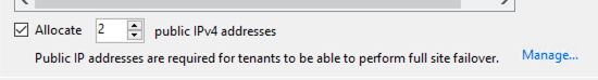
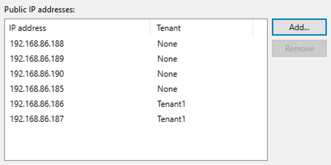
The next step is to specify public IPv4 addresses, which can be used to reach the VMs from the internet after the failover. Setting up a public IP enables a Destination NAT, allowing both internet and internal VLAN to be accessed from the internet if a public IP is enabled.
Configuring Tenant side
Just like on the service provider side, the first thing we will do is set the tenant-side NEA password so we can log in to the NEA if needed.
As mentioned earlier, the tenant side will have one NEA created for each production network. In my lab setup, I have two LANs and two NEAs associated with them.
The first step on the tenant side is to create a replication job. You don’t necessarily need to specify any network mapping, as Veeam will automatically map VMs to a DR network as mentioned in the user guide.
The next step is to create a failover plan. You can initiate this failover plan either from the tenant side or from the service provider side (in the event that the production side is down and inaccessible).
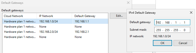
For default gateways, after the first replication job, Veeam will automatically detect all the networks and populate this section. However, you can edit this if needed.
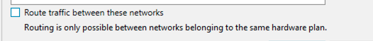
An important checkbox is available here, which enables communication between VMs from different networks on the DR side by creating the necessary routes in the NEA.
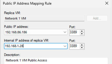
Another setting that needs to be configured on the Failover plan is the public IP assigning. In my SP settings I have allocated two public IPs for this tenant and I am creating mapping here.
Networking
Service Provider side
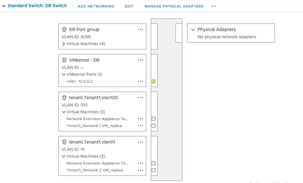
Once all the configurations are done and you have run the replication once, this is how the networking looks:
Service provider side
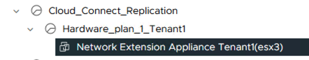
The NEA is created with one NIC on the service provider’s production side and has 2 NICs each in VLANs 100 and 111.
Note: We set a broad range for the Internet and internal VLANs and configured this tenant to have one Internet and one internal VLAN. Consequently, Veeam picked the first available VLAN ID in each range
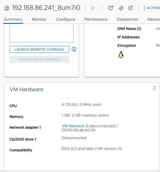
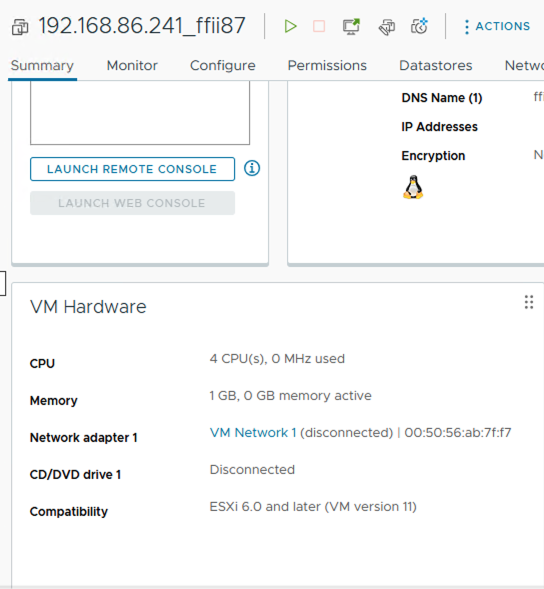
Tenant Side
On the tenant side I have two NEAs created. Each of them connected to the relevant production networks
Now that replication is set and ready to go, let’s see how the failover looks in the next blog.
References
https://helpcenter.veeam.com/docs/backup/cloud/cloud_replication.html?ver=120