This is the continuation of our DRaaS series! In Part 1, we discussed configuring DRaaS components on the service provider side and setting up a failover plan on the tenant side.
In this section, we’ll dive into the failover process and share observations from the NEA during different failovers.
As we covered in the previous blog, tenants can perform two types of failovers:
- Full site failover
- Partial failover
The role of the NEA as a network appliance changes depending on the type of failover.
If you haven’t read the previous blog post yet, I highly recommend checking it out first, as we’ll be continuing from the same scenario.
Full Site Failover
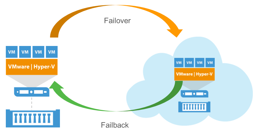
A tenant or a service provider would initiate a full site failover when the tenant’s entire production environment is down or expected to go down. This can be done by running a failover plan either on the tenant side or on the service provider side.
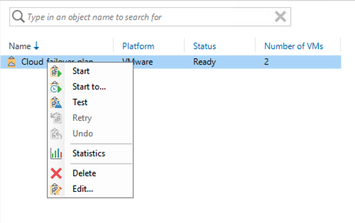
The start option will pick the latest restore point, while the start to option allows you to select a specific point in time. When you initiate a full site failover, Veeam will automatically turn on the NEA on the service provider side. This NEA will now act as a firewall for the tenant workloads.
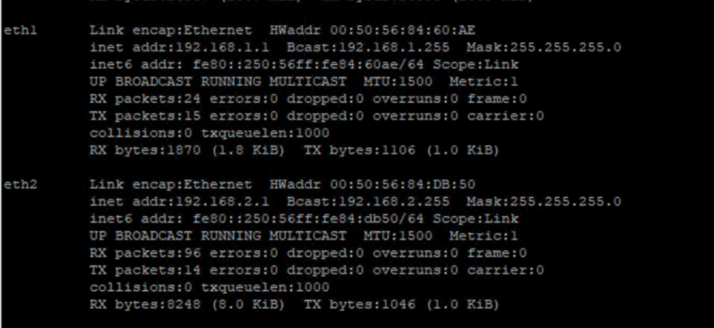
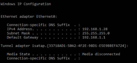
As we discussed in Part 1 of the blog, the NEA’s external interface can be placed in the DMZ, where it will be assigned a public IP (the public IP assigned to the tenant). The NEA also gets a separate NIC for each of the production networks.
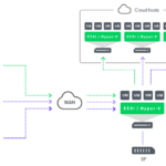
Below is a conceptual diagram of my lab during the full site failover.
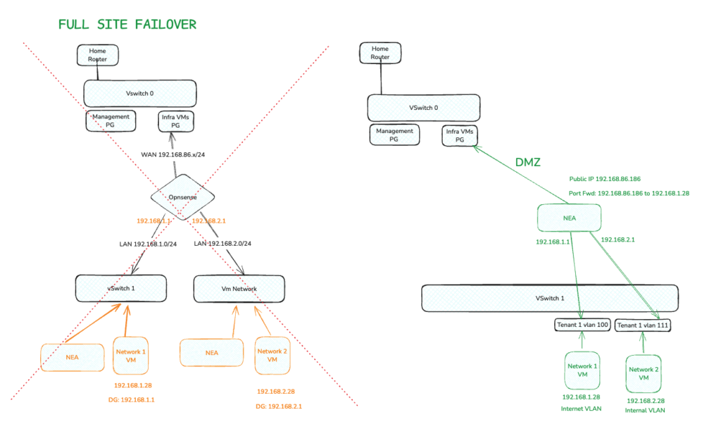
Since the NEA acts as a firewall, each of its interfaces aligned with the production network will hold its default gateway.
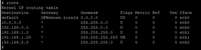
Below is how the NEA’s route table looks. Note that there is a dedicated route created for 192.168.1.28. This is because it is the VM that is part of the internet VLAN and has a public IP with port forwarding enabled for RDP, as per the failover plan we created on the tenant side.
Now, let’s dive into the fascinating world of NATing.
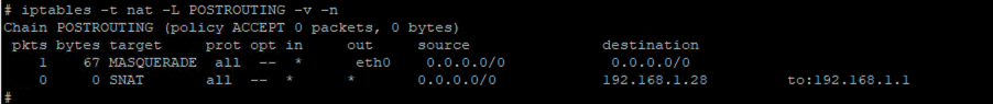
As I mentioned in my previous blog, Veeam will create a Source NAT (SNAT) for the internet VLAN but not for the internal VLAN. To understand why, we need to explore the differences between Source NAT and Destination NAT, and when they are applied.
Source NAT (SNAT): The destination IP remains the same, while the source IP changes. This process changes the private address to a public address when leaving the local network and occurs after the routing decision.
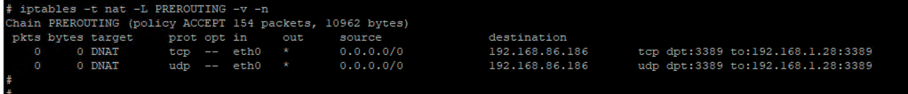
Destination NAT (DNAT): The destination IP changes, while the source IP remains the same. This process changes the destination public address to a private address when entering the local network and occurs before routing.
Since the VMs in the internet VLAN need to access the internet, Veeam creates a Source NAT. This ensures that all private IPs in the subnet are translated into a public IP when trying to access the internet. As this happens after routing, here’s how a SNAT would look in the NEA:
Similarly, when you have a public IP enabled, there may be a server under the NEA that needs to be accessed from the internet. To achieve this, we need to translate the public IP through which the service is accessed into the private IP of the VM in the LAN. Since this happens before routing, DNAT in the NEA will look like the following:
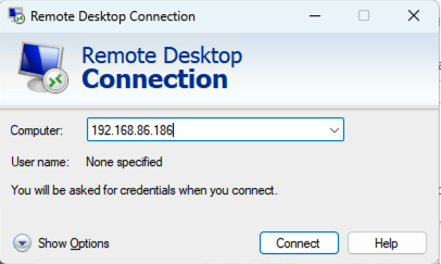
Note: We set the public IP 192.168.86.186 to port forward 2289 to the server in the LAN with the private IP 192.168.1.28.
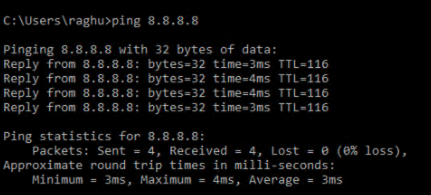
Now if I login to the VM in internet VLAN, I can reach the internet.
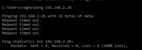
However since I have inter-VLAN routing disable in the failover plan, I won’t be able to reach the VM in the internal VLAN
Similarly, if I log in to the VM in the internal VLAN, I am unable to access the internet because there is no Source NAT created for this LAN (192.168.2.0/24).
To test the DNAT, I tried accessing 192.168.86.168 on port 3389 and was successfully port forwarded to 192.168.1.28.
Partial failover
Partial failover is executed when only one or a handful of servers need to be failed over, while the remaining servers and workloads continue to operate in the production environment.
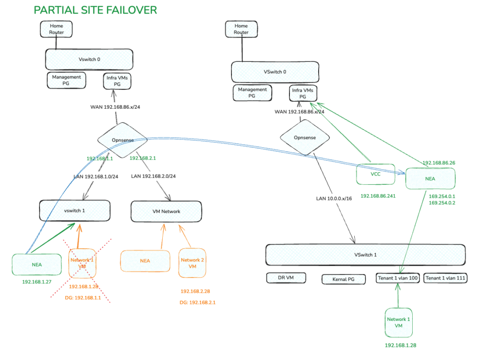
This presents the challenge of establishing communication between the VMs in the same LAN. For example, if you have Server 1 and Server 2 in the 192.168.1.0/24 network in production, and you failover Server 2 to the DR site, Server 1 will look for Server 2 within the same broadcast domain. Therefore, they need to communicate on Layer 2 over a Layer 3 network.
To achieve this during partial failover, we use NEAs on both the tenant and service provider sides. Veeam creates a Layer 2 tunnel between the two NEAs to establish an OpenVPN connection, facilitating Layer 2 communication.
Here is a conceptual diagram of my lab during partial failover:
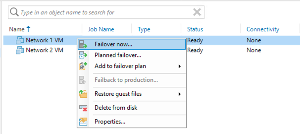
To initiate partial failover, you can execute failover on an individual or group of VMs from the tenant VBR. In this case, I am failing over Network 1 VM.
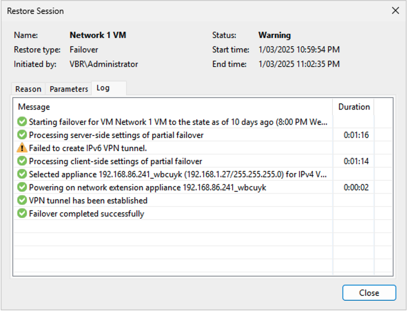
This will turn on one of the two NEAs

In the failover statistics window you get to see a tunnel getting established
And in the cloud connect server, Under history -> Cloud connect, you get to see an active VPN tunnel with data transferred over it.

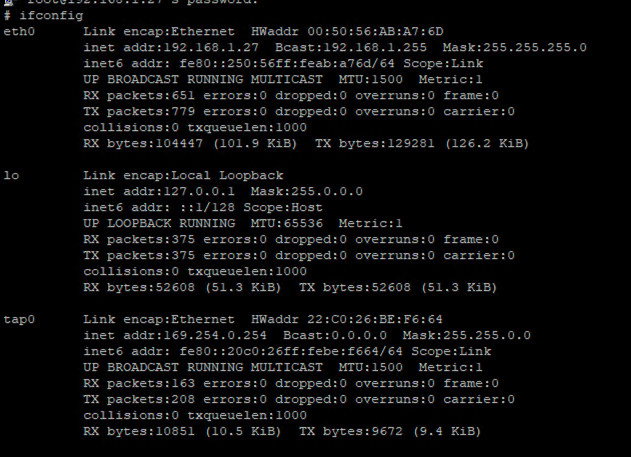
Now, if we log in to the tenant-side NEA, you will see three interfaces, including one that connects to the production network (uplink) and a VPN interface (tap 0).
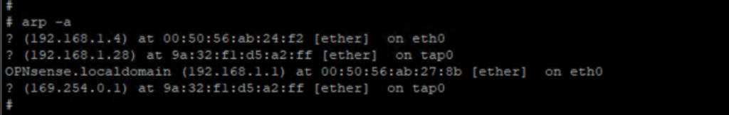
Since this is a Layer 2 over Layer 3 setup, you can see that the ARP table on the tenant-side NEA has learned the failover VM over the tap interface.
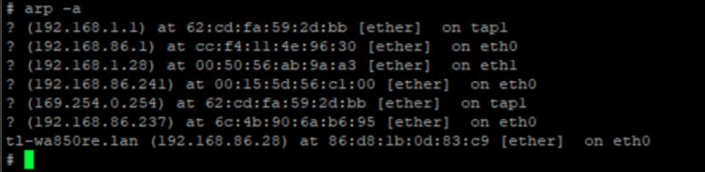
Similarly the Arp table of the service provider side NEA would have the default gateway of the failover VM learnt over the VPN tap interface.
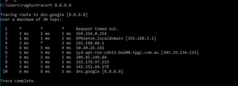
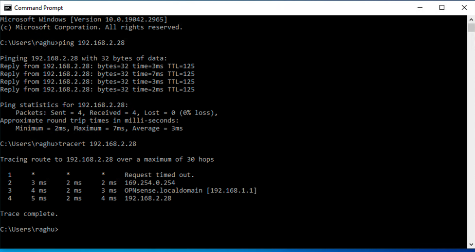
As some of you might have guessed, if the failed-over VM on the service provider side needs to access the internet, the traffic will flow as follows: VM -> Service provider NEA — VPN Tunnel -> tenant NEA -> tenant-side firewall -> internet. Below is a sample tracert command:
Similarly, the failover VM on the service provider side can also reach the other VMs on the production network over the same VPN tunnel, even if the VM is in a different LAN in production, as long as interVLAN routing is enabled on the production side.
Conclusion
In conclusion, the Network Extension Appliance (NEA) in Veeam DRaaS plays a crucial role in managing network aspects during failovers. As I mentioned earlier, I am not a networking expert; this blog is a result of my self-learning efforts. I hope sharing my experiences and insights will help others who are in the same learning phase.
References
https://helpcenter.veeam.com/docs/backup/cloud/cloud_replication.html?ver=120